| 3. |
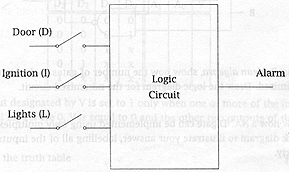
(a) The following diagram shows an
automobile alarm circuit that is used to detect certain undesirable conditions. The three
switches are used to monitor the status of one of the doors, the ignition system, and the
headlights. |
|
|
 |
|
|
Design a logic circuit that takes
these three switches as inputs and activates the alarm when, and only when, either of the
following conditions exists: |
|
|
|
the headlights are on and the ignition is off |
|
|
|
the door is open and the ignition is on |
|
|
Your answer should
consist of: |
|
|
(i) a truth table |
[4] |
|
| minterm |
D |
I |
L |
A |
| 0 |
0 |
0 |
0 |
0 |
| 1 |
0 |
0 |
1 |
1 |
| 2 |
0 |
1 |
0 |
1 |
| 3 |
0 |
1 |
1 |
1 |
| 4 |
1 |
0 |
0 |
0 |
| 5 |
1 |
0 |
1 |
1 |
| 6 |
1 |
1 |
0 |
0 |
| 7 |
1 |
1 |
1 |
0 |
|
|
|
four marks for
a correct table; deduct one mark for each incorrect value assigned to A, to a minimum of
zero marks out of four: the presence or absence of the minterm column should not affect
the marks. |
|
|
[4
marks] |
|
|
|
|
|
(ii) a complete K-map |
[2] |
|

|
|
|
1 mark for
correct K-map; 1 mark for appropriate looping. Award full marks if K-map and looping is
correct with respect to the truth table supplied by candidate - if candidate has made a
mistake at the beginning of the question, then they should suffer for it only once. |
|
|
[2
marks] |
|
|
|
|
|
(iii) a simplified SOP expression |
[2] |
|
|
 |
|
|
two marks; one
for each product; again, if this is correct with respect to the K-map supplied by
candidate, award the marks - they have shown how to translate a completed K-map to a sum
of products |
|
|
[2
marks] |
|
|
|
|
|
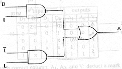
(iv) the logic diagram itself |
[2] |
|
|
 |
|
|
two marks; one
for the AND gates, one for the OR; again, if this is correct with respect to the product
of sums supplied by candidate, award the marks - they have shown how to translate a
product of sums to a logic diagram. |
|
|
[2
marks] |
|
|
|
|
|
(b) Consider the circuit shown
below: |
[5] |
|
 |
|
|
Using Boolean algebra,
show how the number of gates in the circuit can be minimized. Draw the logic diagram for
the minimized circuit. |
|
|
|
 |
|
|
one mark for
each of the above expressions (on the right) appearing the argument |
|
|

|
|
|
one mark for a
logic diagram that corresponds to the last line of the boolean algebra, even if that is
incorrect: e.g., if candidate arrives at A + B, and then draws an OR gate, award the mark
for the logic diagram |
|
|
[5
marks] |
|
|
|
|
|
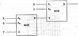
(c) Show how a NAND gate can be
implemented using only multiplexers. Draw a block diagram to illustrate your
answer, labelling all of the inputs and outputs clearly. |
[5] |
|
 |
|
|
one mark for
each correct input to the circuit |
|
|
[5
marks] |
|


