| 4. |
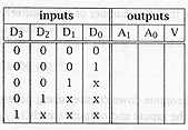
Design a 4-input priority encoder
for the inputs and outputs shown in the table below. Input D3, the most
significant bit, has the highest priority. |
|
|
 |
|
|
The valid output designated by V
is set to 1 only when one or more of the inputs are equal to 1. If all inputs are 0, V is
equal to 0 and the other two outputs of the circuit are not used. |
|
|
(i) Complete the truth table |
[6] |
|

|
|
|
two marks for
each correct column: A1, A0, and V: deduct a mark for each error,
down to zero |
|
|
[6
marks] |
|
|
|
|
|
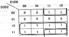
(ii) Draw the K-map for A1
and A0 |
[4] |
|

|
|
|
two marks for
the correct map; deduct a mark for each error, down to zero |
|
|

|
|
|
two marks for
the correct map: deduct a mark for each error, down to zero |
|
|
[4
marks] |
|
|
(iii) Show the simplified Boolean
expression for all 3 outputs |
[4] |
|
|
 |
|
|
one mark for
V, one mark for A, and two marks for A0 |
|
|
[4
marks] |
|
|
|
|
|
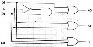
(iv) Draw the logic diagram for
the 4-input priority encoder with the minimum number of gates |
[4] |
|

|
|
|
one mark for
correct input to the OR gate for V, one mark for correct input to the OR gate for A, and
two marks for correct input to the OR gate for A0. |
|
|
[4
marks] |
|
|
(v) How does an ordinary encoder
differ from a priority encoder? |
[2] |
|
In a
priority encoder, the output code corresponds to the highest-numbered input that is
activated; |
[1] |
|
in an
ordinary encoder, only one of the input lines should be activated at a given time. |
[1] |
|
[2
marks] |
|


