|
(a) Describe the difference
between parallel adders and serial adders; your answer
should explain the significance of carry lookahead. What are
the advantages and disadvantages of serial adders over parallel adders? [4
marks] (b) The diagram below shows a serial adder circuit. The two arguments are fed in at A and B, the sum returned at S.
(i) In what order should the bits of the arguments be fed in? [1 mark] (ii) Explain the purpose of the lowest of the three D flip-flops. [1 mark] (iii) What is the
purpose of the input marked Z? Explain how the circuit achieves
the purpose [2 marks] (i) The arguments should arrive least-significant-bit first. [1 mark] (ii) The lowest flip-flop stores the carry out from one stage of the addition to use as carry in for the next stage. (iii) Input Z marks the beginning of the input (1 mark). When Z is low, the carry in is reset for the start of the addition; when Z is high, the carry out from the previous stage is used as the carry in to the next stage (1 mark). [2marks]
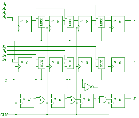
(c) Design a circuit
that can be used to take as input two 4-bit numbers, and feed them
bit by bit to the serial adder. Your circuit should take as inputs
A0, A1, A2,
A3 and B0, B1,
B2, B3, the two numbers to be
added, and S, a signal that is set high for one clock pulse
to make the start of the addition then remains low for the rest of
the computation. You may use shift registers for the inputs. [5
marks]
(2 marks for loading the A inputs into a row of latches, then shifting them out bit by bit; give 1 mark instead if they made some reasonable attempt but didnít get it quite right. 1 mark for repeating the same trick with the B inputs. 1 mark for obtaining the Z output correctly Ė actually, the row of latches here is unnecessary, as just Sí will do. Final 1 mark for clarity and labeling. There are doubtless many ways of doing this; be flexible.) [5 marks]
(d) Design a circuit
that takes as input the output of the serial adder, presumed to be
the result of adding two 4-bit numbers, and collects it to yield a
single 4-bit sum to be read in parallel. [2 marks]
(1 mark for a row of latches, collecting the outputs of the serial adder. 1 mark for labeling and clarity.) [2 marks] |


