|
(a) (i) Give the truth table for a 2
× 4 decoder. [2]

1
mark for correct format, 1 mark for the entries).
(ii)
Draw a circuit implementing this behaviour. [2]
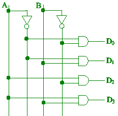
(1 mark for
connections, 1 mark for labelling.)
(iii) Show how to construct a 3 × 8 decoder, using two 2 ×
4 decoders and
other suitable gates. [2]

(1 mark for
connections, 1 mark for labelling.)
(b) The circuit below implements a three-bit adder using XOR gates.
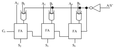
(i) Give the characterisation
table for an XNOR gate. [1]

(ii) Redesign the three-bit adder to use XNOR gates in place of the
XOR
gates. [3]
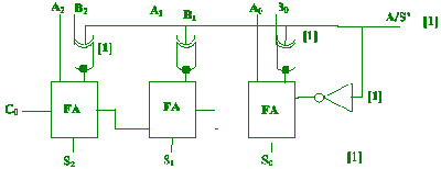
The
Adder/Subtractor Circuit
Guide: 1 mark for connection of A/S’ switch to NOT gate, 1 mark
for
connection of the XNOR gates, 1 mark for clear labelling.
(c) Convert F(A,B,C,D) =  (0,1,3,5,9,11,13,15)
into the minterm form and (0,1,3,5,9,11,13,15)
into the minterm form and
Implement the function with a multiplexer and other necessary logic
gates.
Show the implementation table using A as input and B,C,D
as the selectors.
You need not give the Truth table. [5]
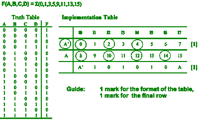
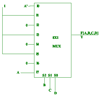
Guide:
1 mark for multiplexer, 1 mark connection to multiplexer, 1 mark for
selector
|


