|
(Sequential Circuits) (15)
(a) Explain the difference between positive-edge triggering and positive-level
triggering of flip-flops. [2]
With positive-edge triggering, the flip-flop
changes state instantaneously,
on the transition of the clock from low to high (1 mark); with positive-level
triggering, the flip-flop changes state continually, as long as the
clock is
high (1 mark).
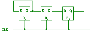
(b) Using three D flip-flops design the arithmetic shift right. [3]

The Shift Register
Guide: 1 mark for connections between flip-flop, 1 mark for clock
connection, 1 mark for complete label.
(c) (i) Convert the JK flip-flop to
a T flip-flop. [2]

Guide:
1 mark for the connections, 1 mark for labelling.
(ii) Combine three T
flip-flops together to form a three-bit synchronous
down counter. [4]
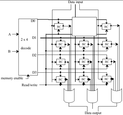
(d) The circuit below is supposed to
be a 4 × 3-memory cell connected to a
decoder. Each binary cell BC behaves as described in Question 1(j).
Complete
the circuit by connecting in a twelfth binary cell. You need not redraw
the
whole diagram; show only the parts you have added. [4]


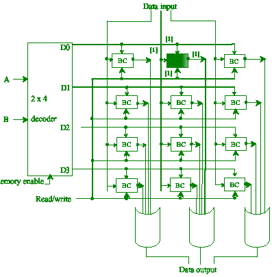
Guide:
1 mark for connection to decoder, 1 mark for connection to input
data line, 1 mark for connection to OR gate, 1 mark for connection
to
read/write line.
|


