| This is an easy question for
candidates who have some intuition regarding flip-flops and sequential circuits; it is
completely unfamiliar, which may help to balance the low degree of difficulty - it will be
interesting to see if candidates feel able to tackle it, and how they perform if and when
they do.
|
||
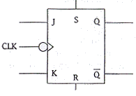
| A universal J-K flip-flop has two
synchronous (clocked) inputs J and K, two asynchronous inputs S and R, anc a clock input
CLK.
|
||
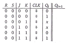
| (a) | When R = 0 and S = 0, the flip-flop
behaves exactly as an simple J-K flip-flop: it will hold, reset, set or toggle the output
depending upon the values of J and K when the clock reaches a negative edge. Using this
information, copy and complete the following characteristic table:
In a table, indicates that the clock reaches a negative edge and x indicates a don't care condition.
|
[6] |
quick and easy: 1 mark per connect row
|
||
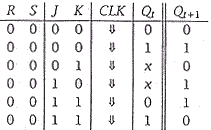
| (b) | When R = 1 then the Q output of the
flip-flop is reset immediately to ), whatever the value of the other inputs; the flip-flop
will change state without waiting for the next negative edge. When R = 0 and S = 1, the
output Q is set immediately to 1; again the values of the other inputs do not matter.
Using this information, copy and complete the following table.
In the table, x indicates a don't care condition.
|
[2] |
if anything, quicker and easier: 1 mark per correct row
|
||
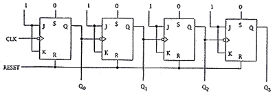
| (c) | Draw a fully label a circuit diagram
to show how 4 universal J-K flip-flops can be linked to produce a four-bit binary
asynchronous counter (a ripple up-counter). Your counter should have a shared reset
input which has the effect of setting all outputs to 0.
|
[6] |
one mark for each of the following features:
|
||
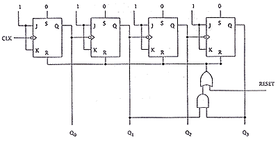
| Draw a fully label another circuit diagram to show how 4 universal J-K flip-flops can be linked to produce a four-bit binary asynchronous counter with a mod number of 10. This counter should return to 0000 after reaching the output 1001. Again, there is a shared reset input which - when set to 1 - will immediately return all outputs to 0. | [6] | |
one mark for each of the following features:
The other features have already been examined in the previous part of the question. An equivalent circuit selecting 0101 (read backward! = 1010 binary) for the RESET should also be considered. However, this is the expected solution. |
