| (a) | Calculate the value of the
expression
and give the result in base 8. |
[4] | ||||||||||||||||||||||||||||||||||||||||||||||||
(11112 + 234 + B9416) ¸ 1610 = (1111 + 1011 + 1011 1001 0100)2 ¸ 100002 = 1011 1010 11102 ¸ 100002 = 1011 1010.11102 = 272.78
|
||||||||||||||||||||||||||||||||||||||||||||||||||
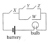
| (b) | The following circuit shows a
controller for a lightbulb using four switches and a battery.
Give a boolean expression describing the state of the lightbulb, in terms of the settings of the switches W, X, Y, Z. Use 1 for a closed (conducting) switch and 0 for an open switch, and 1 for the lightbulb being on and 0 for it being off. |
[2] | ||||||||||||||||||||||||||||||||||||||||||||||||
X (YZ + W)
|
||||||||||||||||||||||||||||||||||||||||||||||||||
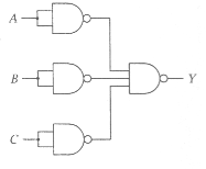
| (c) | Express the following circuit
symbolically.
Redraw the circuit using a single gate, and express the new circuit symbolically too. |
[3] | ||||||||||||||||||||||||||||||||||||||||||||||||
| The circuit implements the expression
|
||||||||||||||||||||||||||||||||||||||||||||||||||
| (d) | By constructing a Karnaugh map,
find a minimal product-of-sums expression for the function F (A, B, C, D) = |
[3] | ||||||||||||||||||||||||||||||||||||||||||||||||
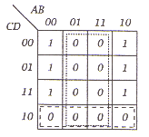 _ _ so the minimal product-of-sums expression is B(C + D).
|
||||||||||||||||||||||||||||||||||||||||||||||||||
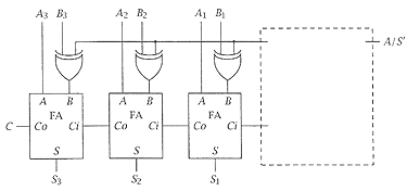
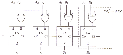
| (e) | Complete the diagram below so
that the device can act as a 4-bit adder/ subtractor with A/S' as the switch. (
Each full adder FA has inputs bits A and B and carry in Ci, and
output bit S and carry out Co. The switch A/S' selects addition
if it is high, and subtraction if it is low.) Show all the relevant components and
connections to and within the dotted box.
|
[6] | ||||||||||||||||||||||||||||||||||||||||||||||||
|
||||||||||||||||||||||||||||||||||||||||||||||||||
| (f) | Give the truth-table for a 1-to-8 demultiplexor, with a data input A, three selector inputs S0 to S2, and eight data outputs B0 to B7. | [2] | ||||||||||||||||||||||||||||||||||||||||||||||||
... |
